From inside (document excerpt):
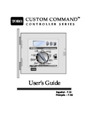
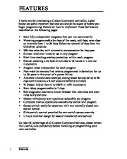
CUSTOM COMMAND CONTROLLER SERIES TM User’s Guide Español – P. 31 Français P. 65 FEATURES Thank you for purchasing a Custom Command controller. Listed below are some important features you should be aware of before you begin programming. Details on how to implement these features are described on the following pages. · · Four fully independent programs that can run concurrently Watering programmable for days of the week, odd days, even days or intervals from 1 to 30 days. Selective removal of days from the Odd/Even schedule 365-day calendar, with automatic compensation for leap year Sixteen total start times to use in any program Start time stacking overlap protection within each program Station watering time from 0 minutes to 10 hours in 1-minute increments Program erase independent for each program Non-volatile memory that retains programmed information for up to 30 years in the event of a power failure Accurate time and date retention during power failures for up to 90 days continuous via a 9-volt alkaline battery (included) % Season Adjust from 0 to 200% in 10% increments Rain delay programmable to 7 days Self-diagnostic electronic circuit breaker that identifies and overrides faulty stations Master valve/pump start operation selectable per program Complete manual operations available by station and program Sensor switch-ready for operation with any normally-closed rain switch device Slide switch control provided for rain switch sensor override Unique modular design for ease of installation and service To take full advantage of all Custom Command features, please review the User’s Guide completely before installing or programming your new controller.
Lawn Mowing User Manual Free Download. Power Lawn Mower Free Instruction Manual Download PDF.
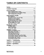
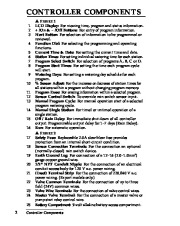
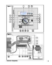
i Features TABLE OF CONTENTS Features i Controller Components .23 General Information 46 How the Backup System Works .4 How the Electronic Circuit Breaker Works .5 How the Sensor Feature Works .6 Programming the Controller .715 Getting Started .79 Setting the Current Time and Date .10 Erasing Any Prior Programs .11 Setting the Station Run Time 11 Master Valve/Pump Start On/Off 12 Setting Program Start Times 1213 Selecting the Days to Water 1315 Operating the Controller .1518 % Season Adjust 15 Manual Operations .1617 Off and Rain Delay 1718 Installation Procedures 1924 Selecting an Installation Site .19 Mounting the Controller .20 Installing Electrical Conduit 20 Connecting Valve Wiring 21 Connecting an Optional Pump Start Relay 22 Connecting an Optional Rain Switch Sensor .23 Connecting an Earth Ground 23 Connecting the Power Wires .24 Appendix A – Troubleshooting 25-26 Appendix B – Fuse Replacement 27 Appendix C – Specifications 28 Warranty .29 Table of Contents 1 CONTROLLER COMPONENTS FIGURE 1 LCD Display: For viewing time, program and status information. + /On & /Off Buttons: For entry of program information. Next Button: For selection of information to be programmed or reviewed. Function Dial: For selecting the programming and operating functions. Current Time & Date: For setting the current time and date. Station Times: For setting individual watering time for each station. Program Select Switch: For selection of programs A, B, C or D. Program Start Times: For setting the time each program cycle will start. Watering Days: For setting a watering day schedule for each program. % Season Adjust: For the increase or decrease of station times for all stations within a program without changing program memory. Program Erase: For erasing information within a selected program. Sensor Control Switch: To override rain switch sensor input. Manual Program Cycle: For manual operation start of a selected program watering cycle. Manual Single Station: For timed or untimed operation of a single station. Off / Rain Delay: For immediate shut down of all controller output. Programmable output delay for 17 days (Rain Delay). Run: For automatic operation. v FIGURE 2 Safety Fuse: Replaceable 2.0A slow-blow fuse provides protection from an internal short-circuit condition. Sensor Connection Terminals: For the connection an optional (normally-closed) rain switch device. Earth Ground Lug: For connection of a 1216 (2.01.0mm2) gauge copper ground wire. 1/2 ” NPT Conduit Nipple: For the connection of an electrical conduit access body for 120 V a.c. power wiring. (Inset) Terminal Strip: For the connection of 220/240 V a.c. power wiring. (Export models only.) Valve Common Terminals: For the connection of up to three field (24V) common wires. Valve Wire Terminals: For the connection of valve control wires. Master Valve Terminal: For the connection of a master valve or pump start relay control wire. Battery Compartment: 9-volt alkaline battery access compartment. 2 Controller Components Figure.
Wikipedia’s page for Toro Company
Company Web Site: www.toro.com


 Toro Custom Command Metal Owners Manual - 1 of 32
 Toro Custom Command Metal Owners Manual - 2 of 32
 Toro Custom Command Metal Owners Manual - 3 of 32
 Toro Custom Command Metal Owners Manual - 4 of 32
 Toro Custom Command Metal Owners Manual - 5 of 32
 Toro Custom Command Metal Owners Manual - 6 of 32
 Toro Custom Command Metal Owners Manual - 7 of 32
 Toro Custom Command Metal Owners Manual - 8 of 32
 Toro Custom Command Metal Owners Manual - 9 of 32
 Toro Custom Command Metal Owners Manual - 10 of 32