From inside (document excerpt):
PSC Inducer Motor Kit Cancels: IIK 398A-35-33 IIK 350M-35-4 10-1-93 Installation Instructions Part No. 317292-752 NOTE: Read the entire instruction manual before starting the installation. INTRODUCTION This instruction covers installation of the Permanent Split Capacitor (PSC) inducer motor kit, Part No. 317292-752 for use in gas-fired, condensing furnaces. See the appropriate section for details on your furnace model.
Heating, Ventilating and Air Conditioning User Manual Free Download. HAVC Operator’s Manual. Gas Furnace and AC Free Instruction Manual Download PDF.
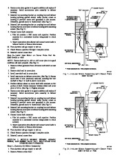
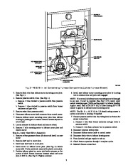
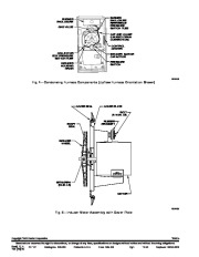
Section I: Models 398A, 399A, 58DX, 58DXA, 58DXC, 58SX, 58SXA, and 58SXC; 46-3/16-in. tall Gas-Fired Condensing Furnaces. Section II: Models 340MAV, 350MAV, 490AAV, 58MCA, and 58MXA; 40-in. tall Multipoise Condensing Gas Furnaces. SAFETY CONSIDERATIONS Installing and servicing of heating equipment can be hazardous due to gas and electrical components. Only trained personnel should install or service heating equipment. Untrained personnel can perform basic maintenance functions such as cleaning coils, or cleaning and replacing filters. All other operations should be performed by trained service personnel. When working on heating equipment, observe precautions in literature, on tags, and on labels attached to unit. Follow all safety codes. Wear safety glasses and work gloves. Have a fire extinguisher available. INSTALLATION SECTION I: MODELS 398A, 399A, 58DX, 58DXA, 58DXC, 58SX, 58SXA, AND 58SXC; 46-3/16-IN. TALL GAS-FIRED CONDENSING FURNACES. NOTE: If the inducer cover plate or wheel require replacement, use inducer motor kit Part No. 309868-754. This kit may be used on furnaces with inducer motor cover plate Part No. 308118-402, 403, or 405. (See Fig. 1 and 2.) The cover plate part no. is located on motor side of cover plate. Step 1–Remove Old Motor Assembly 1. Turn electrical and gas supply to unit off. 2. Remove control access door. 3. Disconnect wiring from motor. 4. Remove screw securing motor ground wire and inducer control box ground wire (when used). The ground screw may be located either on blower shelf or on top mounting bracket of inducer assembly. (See Fig. 3.) 5. Remove screws securing left mounting bracket to collector box and plastic inducer housing. 6. Remove screw securing top mounting bracket to coupling box. (See Fig. 3.) 7. Remove 8 screws securing plastic cover plate to inducer housing. Save top mounting bracket. (See Fig. 3.) 8. Carefully remove motor assembly from inducer housing. 9. Loosen setscrew in inducer wheel and remove wheel. NOTE: One of 3 bolts securing motor to inducer cover plate threads into plastic plate. Locate and mark this bolt before proceeding. 10. Remove 3 bolts securing motor to inducer cover plate assembly and remove motor. Step 2–Install New Motor on Cover Plate Part No. 308118-402 1. Remove rubber grommets from old motor and install on new motor. QUANTITY 1 1 Before beginning any installation or modification, be sure main electrical disconnect switch is in OFF position. Failure to follow this warning could result in electrical shock, personal injury, fire, or death. DESCRIPTION AND USAGE Use this PSC motor kit to restore units with an inducer motor requiring replacement. This kit is designed to allow replacement of inducer motor ONLY. This kit contains the following items: Table 1–Kit Contents DESCRIPTION Motor Capacitor Slinger Ring* Foam Rubber Seal* Harness (Amp Connector) Harness (Molex) Connector Moisture Shield Installation Instructions PART NO. HC29CB115 HC91PD001 308146-201 308588-204 320756-301 302755-301 316790-301 IIK 350M-35-4 2. Remove old foam rubber seal from cover plate and install new foam rubber seal.


 Carrier Owners Manual - 1 of 4
 Carrier Owners Manual - 2 of 4
 Carrier Owners Manual - 3 of 4
 Carrier Owners Manual - 4 of 4