From inside (document excerpt):
(KI KIA MOTORS 2003 Owner’s Manual KIA, THE COMPANY Now thai you are lhe owner of a Kia vehicle. you ” II pmbahly be asked:l lOT of quc. “tions, aboul your vehicle and the company like ‘ ” “Vhul is a Kia? “. “Who is Kia’!’ “. ” Vhat does ‘Kia’ meanY’, Here are -;orne lUlSWCJ!,. First. Kia is the oldcsl car company in Korea. Ii’s a company !hat has thousands of employees focused On building high-qualil)’ vehicles al alTordable pnces because the employees own a significant percentage oftbe company.
User and Operator’s Vehicle Manual Guide. Free Auto PDF Manual Download. Years covered by this manual: 2003.
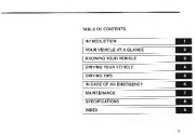
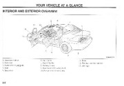
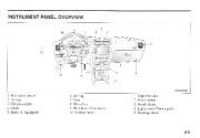
The firsl syllable. Ki. in the l. ord “Kia ” means ’10 arise from to the world ” or “to ( “OffiC up oU( of 10 the world “, The second syllable. a. means “Asia “. Sn, lhe word Kia. means ‘1.0 ari:-,c from ” or “to come up OUI of Asia 10 lhe world “, FOREWORD Thank you forchoo:.ing a Kia vehicle. Vnen you require cnil·e. remember Ihat our authorized Kia dealer knows )our chide best Your dealer ha .; ractory-train d let’hnicians. t :/,;ommcnded spe :iallulIk genuine Kia replacement pans. and is dcdicmoo to lour complete :.ali,foclion. BI.:t:au.-e subsequent Ownt ” require this Illlportant infomlatioD as well. this public:nion !’>hfRJIJ remain wilh the chide if 11 sold. the right to discominue or change -;pcL’ifkatiolls or design al any time wimout notice lind without ineuning any obligalioll. If you ha c qu :stiolls, always check ith your Kia Dealer. We assure )ou of our continuing iniereSl in your motoring plc:c.ure:md !>atisfactioll in )our Kia vehicle. 2002 Kia t lOIors Corp. This manual co ‘ers all L GENTIS models and v.il1 familiarize you ilh operolion. maintenance and safely infonnation about your new chicle. It is uppletllel1 cd h} a W:urant} and Consumer Information Manual th’l’ pr(wides important AU rights resened. Reproduction by any means, electronic Qr mechanical. including photocopying. recording. or by lln) infonmuion lol()rage and retric’ al lo) lotcm ur translation in whole or pari i), nol penniued without wrillen authorization from Kia i’v n1(lrs Corporation. information on all warranties rcganHn ) llur ‘ehkk. Wo: utg. YOu tu rcau these publications careflilly lmd rnllow the nX;llmmcndmiolls to help d’iSUI’C eJ’joynble and afc operation of YOlll’ new vehicle. Printed ill Koren CAUTION S ‘cre Kia llffers 11 great vmicly of options ib V:ltious m()dd. cOl1lpOn ‘IIL :lnd femurc for engine and transa:dc damage may result from the usc of l)f)Qr quality fuels and lubricants that do 1101 meet Therefort’, the equipment do.: “l.:rihcJ in this manual. along with the various illu tralions, may nm all he applkable to your parlicular vehicle, The information and “pccifi :atilln included in this manual were accurate at me timc (if printing. Kia l loton. rc nc Kia specification. You must always LL “e hi h qualit · fue.ls and lubricants that IUffl the specilicalions lioded on page 7· 3S in the Maintenance sel.1ion and page 5-1 in the Dri ‘ing tips section of the O’mer’s ; hllltlul, TABLE OF CONTENTS I=IN T R O::=:DU C T IO N :; = =_ [=Y=O=U R V=E H=IC L=E A=T A ::G LA N=C=E ==_ I=:K N :O::;:;W IN G YO U R VE::;:;H IC:=:L:=E _ I DRIVING YOUR VEHICLE I=:D ::R==IV==IN G=:T==I : : : : : S = = = = = = = = = _ P liN CASE OF AN EMERGENCY MAINTENANCE I SPECIFICATIONS == – ‘ _ I_IN_D_E_X – I :; ;:;: = ii INTRODUCTION HO To Use This Manual .· .· .1·2 _ VehIcle Break-In Process ·· 1·3 1-1 INTRODUCTION HOW TO USE THIS MANUAL We want tu help you gel the greatest The layout (If the manual is provided in the Tahle of Contents. possible driving pkasurc from your vehicle. Your Owntl ” ‘1:111 Ull 1 cun assist you in muny ways. We strongly urge y()U Ln review tIle elllire manual. Howcvcr. in order ” to prevent dC,llh or injuries. at the very 1e I 3 , 5 9 5 7 MMSA2001 I. Reat ‘icw min “or 2. Sum I pr 3. Sunroof /If 1.:.4uipped) -I. Seat b. Tail-lighls 7. t1el liller lid R Parkmg braJ .c 9. Rear door child “akl lock 10, Po er inuo v. ilchc. J I. Duor 12. Outside re:llvjcw mirror 13. Air hags 5. Spare lire 2-2 INSTRUMENT PANEL OVERVIEW 4 7 MMSA20011 1. In.peed also causes Ihe air bags to expand with a gn. “‘U1 deal of fon;c. The spet “d of thh inflation has been t.Iclermined by the Canudian Motor Vehicle Safety Standard ” (Ovl ” l58) to I’edllce the likelihood of sClillllS or lifethreatening injuries and is thus a lllllndlltol)’ pan of air b.lg de:.ign. Thus, air hag inflation could also .:ause injUlies whieh nonn:llly can include faci “l ahr:.t:.inns. bruises and hrokcn bones, However, lhere are e ‘cn circumstances under which contact ,,-ith the stl.’ering wheel air ba C;dn cause [;dtal injuries, espcciaU)’ if the occupant is positioned excessivel)’ close to the steering wheel. YOt: IllST ALWAYS SIT AS FAR BACK FROM TH “F: STEER.l1 (; WHEEL AIR BAG AS l’OSSL8LE, WHTLE STILL MAl TAl Il {; A COMfORTABLE SEA’J’l! ‘C OSmON FOI< COOD VEHH':U: COi TROL, Dl ORDER TO REDljCE THE JUSK OF [ '.TURV ORUf mclll. use only a gPlluine Kia cap. A n incorrect fuel filler cap can result in a serious malfunction IIf the fuel s)'stem or ('mission control S)'SIE'm. Correct replacemeut caps are a "ailablc al Authorized Kia Dealcl. 3·57 KNOWING YOUR VEHICLE STEERING WHEEL HORN MIRRORS OUTSIDE REARVIEW MIRROR Your vehicle. is equipped with both lefthand and right-hand outside rearview minoTs. The mirrors can el1hcr be adju.'tLcd remotely with the conlrollc 'CTh or remole switch. depending on toc Iype ynur vehicle has. The mirror heads can be folded rearward to prevenl damage when w.,ing an automatic car wash or passing another vehicle in a narrow 1'>trcCI. ‘ ” NOTICE Do not scrape ice orr the mirror faCE'; Ihis rna)’ damage the surface of the glass. If ice should restrict movement of the minor, do not force the minor to adjust it. To remoH’ ice. lLW a de-ieer spra ‘. or a sponge or soft cloth with ‘-ery warm water. To sound the horn. press ihc. horn symhol on your sleering wheel. CAUTION The right outsidl’ rcarview mirror is COIlYeX, Objecl seen in the mirror are closer than they appear. When changing laltes, use }’our interior re:arvie ‘ mirror or direct obsen’utiun to determine the actual distanct.’ of follo ;ng nhides behind you. 3-58 OUTSIDE REARVIEW MIRROR HLECTRIC REMOTE CONTROL I. , ll0ve the selector switch to the right (l! ” left to activate (he adjusting mechanism for the corresponding nunor. ,;, NOTICE The mirrOL5 stop moving when they reach the maximum adjusting angles. but the motor continues to operate while the switch is depressed. Do not depress the switch longer than necessar} or the motor may be damaged. 2. Adjust the minor angle hy depressing the min’llr adjustment control switch in The desired direction. 11Lis switch. located on the anmcsl of the driver’s door. Controb the adjustments for both right and left outside mirrors, To in the rear seat to interfere with )’our line of vision through the rear window. f JI The outside rearvicw mirror heal!';1 ” aUlOllHllically turns itsdf orr aner 2() minlLlcs. M 1SA3(l5J 3-60 Electric type (if equipped) Type A TypeB The ClcCllic day/nighl n::arvicw mirror automatically controls the glm’c Ii-om the hCltdlights oj ” the car hehind you. AdjllSl Type B the rearview minor to the desired CAUTION Do not place objects in the rear seat or cargo area which would interfere with your vision out the I’car window, position. MMSA3()7 TypeA TIle electric day/night reafview m.irror JUlomatically conlrol the glare Ii-Om the headlights of the car hchind you. Adjust the ITarvicw mirror to the desit “eel positiun. Press the “0′- button 10 {urn the au[oTl1atic- dimming funclion off. The mimlf indicator light will turn off. Press tile “T ” button to turn the ,H1101ll,s: Turn lhe ignition kc} to lite ON p.:lJ>ition. Pull Ihe sunroof fuse nUl from the main fuse hox in engine compartment and reinstall it. Depcc!’.!’. the from portion of sunroof switch and hold it during 5 SI ‘Comh. SUNSHADE (IF EQUIPPED) I. Removc the retangular plastic lcns in the front of the roof panel. 2. Turn the cross bolt ith a phillip’s screw dn cr counterclockwise to remOVl’ Iht’ from dome light a£SCmhly. 3. Tn.’)cn the hexagonal head wrench provided with the vehide inlo the “lK:kel. Th.is wrench can he found in the glove bo 4. Tum thl’ wrench clockwise to open orcounterdockwisc to clo. The sunshade t’llll be opened with the glas!’. p:.mel aUlOmaticaUy when the glas. panel is slid. To close the sunshade you have 10 do so manually. ” ” ” ” ” CAUTION If )’UU try fo open the sunroof when the temperature is below freezing. point or when th{‘ sunrouf is eO “t roo with snow or ic{‘ the glass p.me or the sunroof motor cuuld be damaged, 3-67 KNOWING YOUR VEHICLE ANTENNA MANUAL ANTENNA (IF EQUIPPED) POWER ANTENNA (IF EQUIPPED) ‘:’ NOTICE Before turning on th(‘ radio. make sure that no one is lIear the antenna. Befllre entering all automatic car wash or a place with a low height clearance, be sure that the antenna is retracted and stored. If the antenna is dirty, be. sure 10 clean it in order to a ‘oid an operation malfunction. , EJ- .;. :;, -. – “‘ ” o _IJ( – f– ‘il7 Your car uses a manual stainless steel antenna 10 rct.:ivc 00111 AM and FM hroadca 1 signuls. PlLlI up lhe antenna USHl£ your fingers. as shown in the drawing. .MSA3065 The antenna will automatically be extended when the radio pmvcr switch is turned “ON ” while the ignitiull key is either in the “ON ” or “ACe ” position. The antenna will automatically be n::lfClctcd emu storeu when cith(;r the moio power ‘iWilCh is turned “OPI- ” ” or the ‘ ” NOTICE Before entering an automatic car wash or a place with a low height clearance, be surf’ that the antenna is full}’ retracted. ignition key is set to the “LOCK ” pns,itioll. 3-68 WINDOW ANTENNA (IF EQUIPPED) CAUTION Do not clean the inner side of the rear window with a harsh glass cleaner or lise a scraper to remove foreign deposits. This could damage the antl’nna elements. Avoid adding metalic coating such as Ni, Cd, and so on. These can disturb receiving Ai’H and FM broadcast signals. LUGGAGE NET (IF EQUIPPED) I J — MMSA3076 When the mdio power switch is turned on while the ignition switch is in either the “ON ” or “Ace’ position. the vehide will n:ccivc both AM 3.nd HI/I broadcast signals through the rlnlCnna in the rear window glass. CARGO NET When you drive with cargo loaded in the trunk room. it can he recured with the luggage net as shown in the illustration. CAUTION Do not overload the luggage net with bulky or numerous items, Securing fragile items with the luggage net while driving is not rCl.:ommcnded. 3-69 DRIVING YOUR VEHICLE Ignition Switch · 4·2 Starting the Engine · . · .·· 4-4 Manual Transaxle · .4-6 Automatic Transaxle ·. .4·7 Brake System ,. .·.·. 4-12 Power Steering ·.· 4-18 Tilt Steering , · . p · · · 4 – 1 8 _ Instrument Cluster . ·.· 4-19 Gauges · · ··4-20 Warnings and Indicators . ·.· ·.· 4·21 Lightings · · · 4-27 Wipers and Washers ·· .·· 4-30 Rear Window Defroster .· ·. 4-32 Interior Fealures . ·· .· 4-33 Cruise Control .·· .· · _.4-37 Traction Control System .· 4 40 Climate Control System ·· 4 42 WIndshield Defrosting and Defogging (Manual Type) .··. .4·54 Windshield Defrosting and Defogging (Automalic type) · .·.··. .4·56 4·1 DRIVING YOUR VEHICLE IGNITION SWITCH ILLUMINATED IGNITION SWITCH IGNITION SWITCH AND ANTITHEFT STEERING COLUMN LOCK ACC (ACCESSOR),) Turning the ignition switch to Ihis position unlocks the steering wheel and will allO some of your vchide’s electrical ‘!!. ON Turning the ignition switch [0 this position allows you l() test your vchidc’s warning lights (except Lht: hrake system warning lighl) to make sure they work lx;fore you Slutl the engine. The ignition key relurns to [he O position once the enginc i started and rClllain in this position while the engine i nmning. 3:1 PUSH WheDC cr a Ul)()f i opened. Iht- ignition 5V. itch will be illuminated for your con cnicnce. pro,iJt’d the ignition sv. itch is not in the “ON ” {X)Silion. The lighl ill go off appro imatcly 10 second:. after closing the door or when the ignition switch j ” · . ” “. ” IGNITION SWITCH POSITION LOCK The steering wheel l lockell 10 prUiect against theft. The ignition key l:an be rerno ‘cd unl} in the LOCK position For vehicles equipped ilh un aurom:uic u n:> The lock release butlon must be depressed white moving the shlfllever. The shift lever can be moved withoUt depressing the lock release button. MM$A4004A 4-7 DRIVING YOUR VEHICLE AUTOMATIC TRANSAXLE OPERATION All normal forward driving is done wilb Ihe shift ber in the D (Drive) position. To mo c lhe shift leyer from the P (Park) position. the ignition s ;tch mml be in the ON position. the brake pL “dal must be dcprcs ed. and the lock release bullon musll;le CAUTION · Do not accelerate the engine in R (RewrseJ or any of the fon, ard positions with the brokes on. When stopped on an upgrade, do not bold the vehicle stationan lith engine power. Usc the se vice brake or the parking brake. Do 1I0t shift from N (Neutral) ur P lI’ark) into 0 (Drh’c) or R (Reverse) when the engine is above idle sJX’Cd. A WARNING – Automatic Transaxle Before leaving the driver’s seat, always make sure the shift lever is in the P (park) position; then set the parking brake fully and shut the engine off. Unexpected and sudden vehicle movement can occur if these ptecautions are not followed in the order Identified. depressed. for smooth o/wmnoll, deprcH the brake pedallt’lJell shifling from N (Nell/ml) 10 {//0 “‘ “01 “11 or RC’I’er.)e gear. 4-8 NORMAL OPERATION P(Park) This position lucks the lransaxlc and pn::vmts the front wheels from rotating. Always come lo a complete stop before shifting into this position. A WARNING · 00 not use the P (Park) position in place of the parking brake when leaving R (Reverse) Usc this position to dt’ive the vehicle Ollckward. the vehicle. Always make sure the shift lever is latched in the P (Park) position so that it cannot be moved unless the lock release button is pushed in AND the parking brake is fully set. A WARNING Shifting into P (Park) while the vehicle is in motion will cause the front wheels to lock and you will lose driving control of the vehicle. CAUTION Ahvu}’s come to a complete stop before shifting into or out of R (Reverse). You may damage the transaxle if ‘ou shift into R while the vl’hicle is in motion, except as explained in “Rocking the Vchicll “‘. N (Neutral) · Turn the ignition switch OFF whenever you leave the vehicle unattended. Never NOTICE The transaxle may be damaged if yOll shift into P (Park) while th£’ yehicle is in motion. leave the vehicle unattended while the engine is running. Unexpected and sudden vehicle movement may occur if these precautions are not taken. leave a child · Never unattended in a vehicle. In tllis position. the wheels and transaxle are not locked. The vehicle will roll freely even on the slightest incline unlc s the parking brake or service brakc arc applied. D (Drive) ‘This is the normal forward driving position. The- transaxle will aulOmatically shift through a four-gear sequence. providing the best fuel economy and power. 4-9 DRIVING YOUR VEHICLE SPORTS MODE * NOTICE In sports mode. only Ihe Cour rorward gears can be selected. To reverse or park the ‘ehicle, mo ‘(‘ the shift I(‘ ‘er 10 thE’ “R ” or ”P” position as required. 10 sport modc, duwnward shifts are made aUlomaticall}’ when the vehicle slows down. When the “ehide slops. lsi gear is automati· call}’ selected. In sports mode. shift points are “aried to upward shift. autom t· ically when the en inc rpm approaches red zone. To maintain the required levels of ‘·chicle performance and safe· t “, the s -stem may not e eculc certain gear shifL “i hen the shift leYer is ope,rated. When drhing on a slipper ‘ road. plL’ih the shift lenr fonurd into the +(Up) position. This causes the transaxle 10 shift into the 2nd gcar which is betlt’r for smooth drh-ing on a slippery road. Push the shift leyer to the ·(Do n) side 10 shift back 10 the hi gear. * NOTICE For smooth and safe operalion, depress the hrake pedal when shifting frolll ”Neutrar’ position or “Park ” position to a forward or re”erse gMr. The ignition key must he in the ··ON ” position and the brake pedal fully depre$ed in order to mo,’e the shift lenr from the “1 “‘(Park) position to any of the other positions. It i always possible to shift from “R “, ‘oN “. “D ” position to the “P “‘ position. But before shirting to “r ” make sure the “ehicle is full stopped to a “oid transaxle damage, Whelher rhe vehicle if, lttuliomtr} liT in motion. spons mode b ‘iclccted by pushing (he shift lever from the “D ” position into the manual gale. To relum 10 “D ” mnge nper.llion. push the 1C( “tOi lever had: into lite main gtllc. In spons mode. tnm ing the shiflle ‘er bad. ardl> and forwards ‘an mal .c gcarJoohirl!i rapidly. In contra:’>1 In a manual tmn.uxle. ,he spon moJc aJltl !’> gcan;hifts wilh lhe shift pedal dcpn::- Up (+) : Push Ihe le ‘er for arU once 10 up nne gear. Down (-): Pull the lever h “ck “un.b unce lo:illift down one gear. hin 4-10 “.’- CAUTION SWft into the “Roo and ‘-p ” posi. MOVING UP A STEEP GRADE FROM A STANDING START Tu move up landing SHIFT LOCK SYSTEM Qr your saJcty. the Autmnalic Transaxlc ha.’i a shifr lock system which prevents shifting thc tram,axlc (lut of P (Park) unless !he hrakc pedal is depressed. To shift the transa;de out of P (Pitrk t: I. Depress and hold thc hmke pedal. 2. Stan the engine or tum the ignition key to the ON …..
nmLinuously or t1:lsh, If Ihe CHECK E GIN’E light begins I(l flash ON and OFF, a more. I>crious problem ·jlh Ihe ECS or el:haust system componenl hal> I “>ccn delected. If this happen.a l1ing. ovcnaking. or passing YOllr vehicle. It shuuld be used whenever emergency ‘ehide is being lOwed. Local regulatiolls /1/(1. prohi1Ji1 1I. illg il ill this !nal/ller. repairs arc hcing made or when the vchide is SlOpped near the edge of a nJUdway. 6-2 3s isltlm:e. If coolant is not boiling out. lillow the engine to idle and lJpen the hlMKJ 10 pem,il the engine to cOlli gmc luully. Iflhe temperature docs not l!O down wim the engine idling. stop engine and allow sufficient time for it to cool. ·L The cllolant level should thcn he cheded. If the level in the reservoir is low. loo for leaks at the rudin.tor hoses and connections. heater hoses 3Ild conntX’linns. radiator. and water pump. If you fmd a major leak or another problem lhal may have caused the engine to overheat. do nol operate lhc engine until the prohlem has heen corrected. Call an AUlhorized Kia Dealer for assislance, Ir you do nol find a leak or olher prohlem. carefully add coolant to the A WARNING – RemOliing Radiator Cap Do not remove the radiator cap when the engine and radiator are hot. Scalding hot coolant and steam may blowout under pressure. This could cause serious injury. EMERGENCY STARTING JUMP STARTING Jump starting can be dangerous if done incorrectly, Thcn;fore. 10 avoid harm lU vourscU’ or damage to your vehicle or hauery. follow the jump starting procedures on the Rl;Xt page. If in doubt. we strongly recommend that you h1l C a compelcnt Icchnician or lowing service jump Slarl your vehicle. ;he If Ihe nlRille frequently ol’erheats. hm’e the cooling Sulem checked alld repaired. :1: NOTICE Use only a Iholt jumper system. YOu can damage a 12 “011 starting motor. ignition system, and other electrical parl hy using a 24- “011 power supply (two 12·volt batteries in series or a 24·volt motor generator set). re rvoir. IN CASE OF EMERGENCY it. WARNING – Battery · Keep all flames or sparks away from the battery. The battery produces hydrogen gas which may explode if exposed to flame or sparks. · 00 not attempt to jump start vehicle 11 the discharged battery is frozen or if the JUMP STARTING PROCEDURE I. Make.’,Ore the booster bauery is 12 volls and lhat ils negative terminal is grounded. 2. Check the clcclrolytc level of each of the ballcry t-clls. 3 If the bou!)ter ballery is in anolher vchicle. do not allow the ‘-ehiclcs to lOuch. electrolyte level is low; the battery may rupture explode. or CONNECTING JUMPER CABLES Connecl c:lblc!> in numerical order and disconnect in reverse orner. (+I® (-)@ B “,, “. bart9l)’ 6-5 IN CASE OF EMERGENCY 4. Tum off all unncl.:cssary eleclrit:al 5. the jumper cables in the exact S(:qucnl’e shown in !he lllustrntion on the previous page. , ” ” “‘Connect Firs!. conm:cl Qne end of a jumper cable 10 the positive lenninal (+) of canlaet anything excepi the correCI hallcry lerminah or the correcl ground. Do not lean over {he baucry when making connections. 6. Stan the engine of Ihe ‘chicle with lhe hooster baUeTy and run it at 2_000 rpm. Then. stan the engine of the PUSH-STARTING A vehicle equipped .ith an autllmalic transaxle (‘annOI be started by pushing. A ,chide equipped with a manuallran axle hould not be push-st 1>pace lhan a regular- -izc lire. 1his tire is. smaller than a cOll ‘cntionill tire and is dc igned for temporary .L “C onl}. CAUT10N This spare tire should be USL’d onl ‘ for VERY short distances. Compact spares should : ‘ ” “EV “ER be used for lon2 drives or extended dislanccs. CAUTION You should drive carefully whcl1 The wmpact spare 5110Uld he inflated to 420kPa (60 p i) the mmpact spare is in usc. The compact spa. “e should be replaced b ‘ the prOI)er cOI1 “entional tire and rim at the first opportunif)’. The o ration of ihis vehicle is nOl recommended with more than nne compact spare tire in use at the same fime. ‘ ” NOTICE Chl’ck the inllatioll pressure after installing the spure tire. Adjust tn the specified pn:ssure. a. Tire: 420 kPa(60 psi) Tn prel1ellf the jack, jack helud/e, wheel IlIg Ill/!. wren “h and spClre lire 11’01/1 while Ihe I’r-hiele is i/1 lIlotion. store them properly. niU/ill); 6-22 MAINTENANCE MAINTENANCE Maintenance Services ·· 7-2 Owner Maintenance . 7-8 Engine Compartment . .7·10 Engine 011 and Oil Filler .·. .· .· _.· .7-12 Engine Cooling System . ·. 7-14 Brakes and Clutch .·· .· ·.7-17 Parking Brake , · 7-18 Power Steering ·· .· 7-18 Automatic Transaxle .·· , · 7-19 Lubricants and Fluids . ·· 7-21 Air Cleaner ·. · 7·21 Wiper Blades ·. .7·22 B ttery 0 0 · 0._ ·· 7-23_ Tires and Wheels 000 7-25 Bulb Replacement 7-32 Lubricant Specifications 7-36 Exterior Care _ . _. 7-38 Interior Care. _ _. _ 7-40 0 · 0 · 0 · _ ·· 7-1 MAINTENANCE MAINTENANCE SERVICES You should exen’i c OWNER’S RESPONSIBILITY MAiNTENANCE SERVICE AND RECORD RETENTION ARE THE OIVNER’S RESPONSIBIUTY. You ‘>hQuJd retain documents 10 sbow lhm propt’T matmcmmce ha ” the tread. Thb “hows there is Ic1’>s (han 1.6mm (1116 im:hl oflread remaining 011 the lire. Replace the l;re when this happens. Do not wait for this band to appear across (he enl;re lread before replacing the lire. Tread wear I’IOlCalor rorated. ‘ –_ _I c:=J ‘ ” NOTICE Rotale radial tires Ihal b:H “C an asymmetric tread pattern from front to rear only and not from right to left. During lire mImi on, check the tires for com.:cl b;llal1i e. Check for uneven wear amI damag.e. Ahnonntll wear is usually caused by incorrect lire pressure, improper whet’! alignment. :m oul-of-balance condition. severe bmking or c “cn:: comeling. Newlfead Worn tread t./MSA7021 7-27 MAINTENANCE COMPACT SPARE TIRE REPLACEMENT A (:(lmpact spare tire ha u shooer tread lif than a regular “ile lire Replace il wben yuu e:m the tread car indiC lor 1>.’113 on the lire. The replacement COmp.1l “( spare lire should he the S3mc size ami design tire as the (lile provkkd wilh your new Kill and should be mounted on the a1l1e compue! spare lire wheeL The l’ompaci spare tire is nOI dcsigned (0 he mounlLxI QIl a rcgubr size hcel. and the compact spare lire wheel is not dc h ‘ncd for mounting a rcg.ular sile tire – WHEEL AliGNMENT AND TINE BALANCE In additiun to (,Hlper lire inrlalion. correct hccl illignmcnt hclp to minmize tire “car. Your chide’s a’i nmenl :-.hould t>c { “necked every 12 months ()f l .OUU krn (15.000 mile “J. YOUI’ lin. ” were properly balanced al thc: rUt’lory. t’olll (hl Y mny need (0 be r babnced hefore Ihey cur OU!. II ” y{lU nOlice a consistenl ibr:uion when driVIng. have your Kia Dealer inslX’tl your lirc. , A lire hould alway:o, he rebahmt’ed if it htL been removed from the , heel. :;: NOTICE Improper “‘hrel weights can damage your ,'(‘hiele’s aluminum wheels. Usr only apprond YI heel “eights. 1i’ CltCat(lf IQCIlll()1l ]·28 ‘ ” NOTICE “‘lIen replacing tires, n Yer mix radial, bi’l ·belted. and hias-type tires J II four tires should be of the sallie size. design and construction. Use only the tire Sill’S listed nn the Tin- Label attached to the passcng{‘f’s door. .”lake sure that all tires and wheels are the sallie she and han the same load-carrying capacit)’. Use only tire and wheel combinations recommended on the Tire Label or by an Authorized Kia Dealer. Failure to follOw these precautions can advcrsdy affect the safet ‘ and handling of your vchicle. The use of any other tire size or type may sl’riousl ‘ affect ride, handling, ground clearance, tire clearance, and spccdnmetcf alibration. Driving on ‘orn·out tires is very hazardous and will reduce braking effediveness. steering accuracy, and raction. 11 is best to replace all four tires on. ‘our nhide at the same time. If that is not possibleJ then replace the two front or two rear tires a. a pair, Replacing just one tire can seriously affect whide handling. TIRE SIZE DESIGNATION is marked with a lire You will lleed this inforrnalion when selecting replacement tires for your r.;ar. The following explains what the letters and numbers in the tire size designation mean. Exampk tire size designation 1’205/60R 15 82T P – Applicable vehicle lype (tires marked with the prefix p ” arc intended for usc on passenger cars: however, not all tirc have lhis marking). 205 – Tire width in millimclcrs. 60 – Aspect Ratio. Tlle lire’s Se(’tilln height as a percentage of tire width. R – Tire construction code (radial). 15 – Rim diameter in inches. R2 – Load Index. A numerical code associated with the maximum load the tire can carry. T – Speed Rating symbol. See the speed rating chart in this section for additional infurrnalion. A tirc·. idcwall siJ: tk ignalion. 7·29 MAINTENANCE WHEEL SIZE DESIGNAIION Wheel.s are also marked wilh important information thai yuu need if yOLl c cr need 10 replace one. The following explain1> what the lellCP and numhen; in Sp«d KaliD S ‘mbol. 1a. .imullI Speed 180 I;mItl, Illmpbl S These tcmpemrure grade , are molded on the sidewalls of p':b:.cn,gcr vdude lirc,. Tires available a. ‘landard or optional – equipment on Kia ‘chicle!'; may ‘3ry with respect 10 gl’3de. the. wheel “;7e designation mean. Example wheel SiLC designation: 15 X 6J 15 – Rim diameter in inches. t)- Rim width in inthes. .J – Rim contour designntion. r-I- T H V Z 190 km/hl lllimph) 110 kmlh!l3Omph) 240 kmlh( 1HlIlph Al.lO ‘ -l()klll!h(1-l9Illph) TIRE SPEED RATINGS The following chart below shows man ,. of the diITcrcn( speed ratingl> currelllly used for passenger car tirc The speed rating 1’oymbol is pan l,f (he fire SiLC dl: ignarion on the ,idc.wall of the Itre. This symhol corresponds 10 that tire’s designctl maximum safe Ilper·.I1ing sJX’Cd. UNIFORM TIRE ” QUAUTY GRADING The (0110 -;0£ information relnres to the lire grading system dc ocloped by the Canadiall t-.’IOlor Vehide Safet}’ St&1dard (CMVSSl ror 1T.x.!ing tires b) tread wear, lmetion and IcmpemNre pcrfmnallCc. 7-30 TREAD WEAR The lread car £r3de is a cnmp:uali c rating based on the wear mlc of the lire hen tested under controlled conditions on a specified govemment le.’it cuurse. For example. a lire Braded 150 ould wear one-and-a-hal r till1CS a. ,ell on me gmemment course a a tirr graded 100. The relauve performance of lires depends upon Ihe aelUal conditions of their usc. Variations in driving hahits. sel ” ice pra(;li(:c and differences in ro4ld characteristics and climate may sib’Tlilicanlly affcct performance. TEMPERATURE-A, B fiND C The temperature grades afe A (the hig.h “II. B and c.1 :pfC’ rlling The tirc.’·s resistance to generate heal and to dissipate he:H when tested under controlled conditions un a specified imJuor labomlOry test wheel. SustainL “tI high Icmpcmturc can cause the malenal of the lire to degenerate and reduce lire life. and excessive lempcT:nurc can lead 10 sudden lire failure. Grade C corresponds to a level IIf pcrfonnance thal all passenger vcrucle tires must meet under the Canadian MOlor Vehicle Salely Standard No. 109: Grades A :md A WARNING – Tire Temperature The temperature grade for a tire is established for a tire that is properly inflated and not overloaded. Excessive speed, underinflation, or excessive loading, either separately or in combination, can cause heat build-up and possible sudden tire failure. This can cause loss of vehicle control and death or personal injury. TRACTION – A, RAND C The traction grades, from highest to lowest. are A. Band C. llnd they represent the lirc’s nbility to SlOp on wei pavement as measured under conlmllcd condilil)n. till specified government test surfaces of asphalt and concrele. A tire marked C may have poor traction B represent higher levels of pelfol111am:c on the laboratory h.:sl wheel than the maximum rCljuircd by lnw. pcrfonnance. MAINTENANCE WHEEl- REPLACEMENT When replacing the metal wheels for an}’ rca. on. make sure (he new wheel. arc equivalcnl to the original factory units in diameter. rim width and otTSt:l. BULB REPLACEMENT HEADLIGHT BULB REPLACEMENT · If a bulb becomes damaged or cracked, replace it immediately and carefully dispose it. it. WARNING – Halogen Bulbs · Wear eye protection when changing a bulb. Allow the bulb to cool before handling it. · Halogen bulbs contain pressurized gas. If broken, a halogen bulb will explode and will produce flying pieces of glass. · Always handle halogen bulbs carefully to avoid scratches and abrasions. If the bulbs are lit, avoid contact with liquids. Never touch the glass with bare hands. Residual oil may cause the bulb to overheat and burst when lit. A bulb should be operated only when installed in the headlight assembly. ‘l-CAUTION A wheel thai is nol the correct size may ad ‘etsel)’ affect whl’c1 and bearing lire, braking and stopping abilities. handling chara!’.teristics. ground clearance. body-to-tire clearance. snow chain clearance. spef’domeler calibration. headlight aim and bumper height. 1_ Remove the headlight bulb cover by turning it countcrclocJ, wisc. 1. Disconnect the headlight bulb electrical connector. 7-32 FRONT TURN SIGNAL! POSITION UGHT BUUJ REPUCEMENT FRONT FOG UGHT REPUCEMENT(lF t “QUIPPEDj 3. Un:.n:lp the headlight bulb retaining wIre. 4. Remove Ihe bulb from the three (3) .,lo[s on the headlight a!>sembly. 5. Inswll a new headlight bulb in fhe three (3) slots on the- headlight assembly nnd snap the headlight bulb retaining wire into position. 6. Connect the headliglll bulb ckttl;cal conneclOI’. 7. [ostall Ihe hendlight bulb cover by turning it c1ock. i:,c. 1 Posoiion ighllTum signa!1!tII 2. HIIadIighI 3. Headlight 1. Remove the bollS from the headlighl 2. 3.. 5. O. assembly. Remove the dust covel “. Di:.nmm:ct the light connector. Remove the light bulb. 111:.Cl1 a new bulb and tl1cn connc,:t thc light cQnneCIOT. lmw.1l the dust cover and then reinstall the headlight as.sembly. I. Turn lhe bulb sodeL counterclockwis.e and remove the bulb socket. 2. Insen a /lew bulb in socket. 3. Install the bulb socket. 7-33 MAINTENANCE REAR COMBINATION LIGHT BULB REPLACEMENT 1. Using II 4. Insert a new bulb in the Sllcket. then push the bulb in and rotate it oncquarter fUrn clockwise to lock the DOME LIGHT BULB REPLACEMENT cross-lip crewdrivcr. remove the Cover. bulb in place. 5, Re-install the bulb socker into the rear combination light assembly and rotate it one-quarter tum clockwise to k) :1.: the socket in place. 6. Rc-installlhc cover, _M “‘7ll28 2. Turn the bulh socket counterclockwise and remove it from the hOllsing. J, Push lbe hlilb in. h(:11 fPtate it 0111.:quarter turn c()untcl’cJockwi c ;md remove the bulb from the :-.ockcl. 1. Usi.ng a rIat-blade screwdriver. gently pry the lens from the dome light housing. 2. CflrcrulJy pull the hulb oul of the sll-:kel. J. ulscrl a new bulb in the s()Ckel. -I. Align the lens lahs with the dome light housing nOlches and snap fhe lens into place. 7-34 LICENSE PLATE LIGHT BULB REPLACEMENT , CENTER HIGH-MOUNTED STOPLIGHT BULB REPLACEMENT 4. Re.-install the bulb socket into the cover and l “Otate it one-quarter tllm clockwise to lock the socket in place. 5_ Re-insialllhe cover. £!, () I n. WI.SA7D29 I. Using a Phillips scrcwdri,, r, rernove the 11111 (2) lens mounting screws Uld!he IClls. t o MMSA7030 Rot:lle socket one-quarter [urn counterclockwise and carefully pull the soch:t from the hOllsing. 3. Carefully pull the hulh oul ofthe socket. .t. lmcrl a new hulb in !.he socket 5. Carefully insert the socket into the h()u ing and rolate ;t one-quaner rum cl(l(;kwise. 6. Re-inslall the lens and the two (2) mounting Crcws. 1. Remo ‘e the cover and [urn the hulb socket counterclockwise and remove it from the housing. 2. Push the hulh in. then ! “Olate it onelIuaner turn cOllllterclockwise and remove the bulb from the socket. , lnsen a new bulb in the socket, then push the bulb in and rotate it OllCquartL:f turn c()ltnlcrclm.:kwise and remove the hulb fl’Om tile socket. 7-35 MAINTENANCE TRUNK ROOM LIGHT BULB REPLACEMENT (IF EQUIPPED) LUBRICANT SPECIFICATIONS RECOMMENDED LUBRICANTS To help al -hieve proper engine and powcnmin performance and dumhilily. usc only lubricallls of lhc flJ’OIXT 4ua1i1y. The ,,- “(lrrect lubricants aho help promote engine efficicnC) whkh results in improved fuel economy. Engine nils laheJed Encrg Con C’r “ing Oil arc now a “ailablc. Along with other additional bendi!:>. Ihe)’ cotlfribute to fuel economy by n:JUl:111g the amount of fud lleCC’isliry 10 overcome engine friction. Often, these improvements are difficult fo measure in e ‘eryday driving. but in a year’s lime they can olTer significant cost and energy saving:-. = I. Remove the trunk HKJm lamp l:over using flat blade screw driver. 2. After replacement of bulb. inslall lhe (‘over. 7-36 These lubricants and tluids are re “omm “mieu for u e in vour vehicle. Lubricant Engine oil Classification API Scrvicc 50 or SH Energy con’-trving-II{5W-30) API Service GL-4 (5A.E 75W-9O) SK ATF PSF-ITI SAEJ 703 or FMVSSI16 DOT-3 DOT-4 RECOMMENDED SAE VISCOSITY NUMBER ,;, NOTICE Always be sure to clean the area around any filler plug, drain plug, or dipstick before checking or draining any lubricant. This is especiall)’ important in dusty or sandy arcas and when the vehicle Is used on unpa ‘ed mads, Geaning the plug and dipstick arcas will prevent dirt and grit from entering the engine and other mechanisms that could be damaged. Manual Lransax!c uil’ ” Automatic trasaxlc fluid Power steeri1H! fluid Brakdcllllch Iluid “to sp-m or Diamonu ATF SP-ill Rc! “cr 10 the recommended SAE viscosity numbers on the thi page. Temperature Range for SAE Viscosity …
Wikipedia’s page for Kia
Publisher: Kia Canada www.kia.ca


 2003 Kia Magentis Owners Manual, 2003 - 1 of 222
 2003 Kia Magentis Owners Manual, 2003 - 2 of 222
 2003 Kia Magentis Owners Manual, 2003 - 3 of 222
 2003 Kia Magentis Owners Manual, 2003 - 4 of 222
 2003 Kia Magentis Owners Manual, 2003 - 5 of 222
 2003 Kia Magentis Owners Manual, 2003 - 6 of 222
 2003 Kia Magentis Owners Manual, 2003 - 7 of 222
 2003 Kia Magentis Owners Manual, 2003 - 8 of 222
 2003 Kia Magentis Owners Manual, 2003 - 9 of 222
 2003 Kia Magentis Owners Manual, 2003 - 10 of 222