From inside (document excerpt):
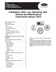
58CT 2 Stage Deluxe Induced Combustion 4 Way Multipoise Furnace Installation, Start up, Operating, and Service and Maintenance Instructions Series 120/C SAFETY CONSIDERATIONS 2 INTRODUCTION 3 CODES AND STANDARDS 5 Safety . 5 General Installation 5 Combustion and Ventilation Air 5 Duct Systems . 5 Acoustical Lining and Fibrous Glass Duct . 5 Gas Piping and Gas Pipe Pressure Testing . 5 Electrical Connections 5 Venting .
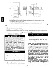
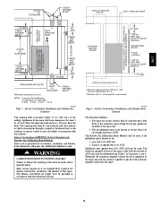
5 ELECTROSTATIC DISCHARGE (ESD) PRECAUTIONS PROCEDURE . 5 LOCATION . 6 AIR FOR COMBUSTION AND VENTILATION . 8 INSTALLATION 10 Upflow Installation 10 Downflow Installation . 11 Horizontal Installation . 11 Filter Arrangement 15 Air Ducts . 15 Gas Piping 17 Electrical Connections . 21 Venting . 26 START-UP, ADJUSTMENT, AND SAFETY CHECK . 35 General 35 Start-Up Procedures 35 Adjustments . 36 Check Safety Controls . 40 Checklist . 41 SERVICE AND MAINTENANCE PROCEDURES . 46 Introduction . 46 Care and Maintenance . 46 Sequence of Operation . 52 Wiring Diagrams . 55 Troubleshooting 55 NOTE: Read the entire instruction manual before starting the installation. Portions of the text and tables are reprinted from NFPA 54/ANSI Z223.1-2006E, with permission of National Fire Protection Association, Quincy, MA 02269 and American Gas Association, Washington DC 20001. This reprinted material is not the complete and official position of the NFPA or ANSI on the referenced subject, which is represented only by the standard in its entirety. REGISTERED CERTIFIED ama ISO 9001:2000 26-1/8 ” (FLUE COLLAR) 28-7/8 ” 25-1/4 ” 22-9/16 ” JUNCTION BOX LOCATION. Two additional 7/8-in. diameter holes are located in the top plate. 2. Minimum return-air openings at furnace, based on metal duct. If flex duct is used, see flex duct manufacturer’s recommendations for equivalent diameters. a. For 800 CFM-16-in. round or 14 1/2 x 12-in. rectangle. b. For 1200 CFM-20-in. round or 14 1/2 x 19 1/2-in. rectangle. c. For 1600 CFM-22-in. round or 14 1/2 x 22-in. rectangle. d. For airflow requirements above 1800 CFM, see Air Delivery table in Product Data literature for specific use of single side inlets. The use of both side inlets a combination of 1 side and the bottom, or the bottom only will ensure adequate return air openings for airflow requirements above 1800 CFM. A04037 NOTES: 1. Two additional 7/8 in. diameter holes are located in the top plate. 2. Minimum return air openings at furnace, based on metal duct. If flex duct is used, see flex duct manufacturer’s recommendations for equivalent diameters. a. For 800 CFM 16 in. round or 14 1/2 x 12 in. rectangle. b. For 1200 CFM 20 in. round or 14 1/2 x 19 1/2 in. rectangle. c. For 1600 CFM 22 in. round or 14 1/2 x 22 in. rectangle.


 Carrier Owners Manual - 1 of 58
 Carrier Owners Manual - 2 of 58
 Carrier Owners Manual - 3 of 58
 Carrier Owners Manual - 4 of 58
 Carrier Owners Manual - 5 of 58
 Carrier Owners Manual - 6 of 58
 Carrier Owners Manual - 7 of 58
 Carrier Owners Manual - 8 of 58
 Carrier Owners Manual - 9 of 58
 Carrier Owners Manual - 10 of 58