From inside (document excerpt):
Downflow Furnace Subbase Installation Instructions Part No. 58DHC900 031 NOTE: Read the entire instruction before starting the installation. INTRODUCTION This instruction covers installation of a floor subbase Part No. 58DHC900 031 designed for use with Model 58DHC, 58DP, 58DR, 58DRC, 58DXA, 58DXC, and 58RAV Downflow Gas Furnaces. The design of the subbase is A.G.A. certified for use with a downflow gas furnace.
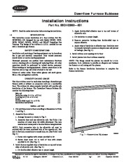
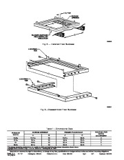
b. Apply double-sided adhesive tape to top and bottom of adjustable rails. c. Cut insulation to proper length. d. Remove protective backing from double-sided tape to expose adhesive. e. Apply strips of insulation to adhesive tape. Insulation must be properly installed to ensure an adequate seal and prevent air leakage. (See Fig. 2.) 4. Install subbase over opening cut in floor. 5. Install plenum into floor subbase assembly. NOTE: The flange around the plenum top should be 1-1/4-in. maximum, 7/8-in. minimum to provide an adequate seal between the furnace or coil casing and the plenum. Refer to the furnace Installation Instructions to complete the furnace installation. SAFETY CONSIDERATIONS Installation and servicing of heating equipment can be hazardous due to gas and electrical components. Only trained personnel should install or service heating equipment. Untrained personnel can perform basic maintenance functions such as cleaning coils or cleaning and replacing filters. All other operations should be performed by trained service personnel. When working on heating equipment, observe precautions in the literature and on tags and labels attached to the unit. Follow all safety codes. Wear safety glasses and work gloves. Have a fire extinguisher available. DESCRIPTION AND USAGE This floor subbase must be used when installing a downflow gas furnace (with or without an evaporator coil) on a combustible floor. The subbase kit, when properly installed, will provide safe installation of the furnace. The Downflow Furnace Subbase Kit contains the following items: Side rail Insulation strips (1-1/4 in. x 92 in.) Locating tab (1 in. x 2-1/2 in.) Screw Double-sided tape(1 in. x 15 ft) Installation Instructions INSTALLATION 1. Cut and frame hole in floor according to dimensions in Table 1 and Fig. 2. 2. Assemble floor subbase. a. Arrange baseparts as shown in Fig. 3. b. Assemble front and rear adjustable rails. See Table 1 for selection of screw holes for width adjustment. The hole number must correspond to the size furnace being installed. NOTE: Each successive hole in the adjustable rail must be matched with the same numbered hole of the opposite rail, first hole to first hole, second hole to second hole, etc. (See Table 1 and Fig. 3.) c. Fasten rails together with screws provided in kit. d. Secure sheet metal tab to back of base with screws provided in kit. (See Fig. 1.) 3. Install factory-supplied strips of insulation on top and bottom sides of adjustable rails. (See Fig. 2.) a. Cut double-sided adhesive tape to proper length.


 Carrier Owners Manual - 1 of 2
 Carrier Owners Manual - 2 of 2