From inside (document excerpt):
Upflow Gasket Kit Cancels: IIK 398A-40-16 IIK 398A-40-34 2-1-92 Installation Instructions Part No.318050-751, through -754 NOTE: Read the entire instruction before starting the installation. INTRODUCTION This instruction covers the identification and installation location of gaskets included in the Gasket Kit. (See Fig. 1.) The Gasket Kit is designed to provide replacement gaskets for the Upflow GasFired Condensing Furnaces.
Heating, Ventilating and Air Conditioning User Manual Free Download. HAVC Operator’s Manual. Gas Furnace and AC Free Instruction Manual Download PDF.
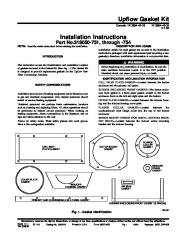
DESCRIPTION AND USAGE Installation details for each gasket are covered in the installation instructions packaged with each replacement part requiring a new gasket(s); therefore, installation information is not provided here. Before beginning any installation or modification, be sure the main electrical disconnect switch is in the OFF position. Electrical shock can cause personal injury or death. IDENTIFICATION AND LOCATION INFORMATION CELL INLET PLATE GASKET–Located between the burner enclosure and the primary cell panel. BURNER ENCLOSURE FRONT GASKET–The burner enclosure front gasket is a three piece gasket located in the burner enclosure front on the left and right sides and the bottom. COVER PLATE GASKET–Located between the inducer housing and the inducer housing cover plate. FLANGE COLLAR GASKET–Located between the combustion-air inlet flange collar and the top of the burner enclosure. MOTOR MOUNT GASKET (FOR METAL INDUCER HOUSING ONLY)–Located between the inducer motor mounting bracket and the inducer housing. SAFETY CONSIDERATIONS Installation and service of heating equipment can be hazardous due to gas and electrical components. Only trained personnel should install or service heating equipment. Untrained personnel can perform basic maintenance functions such as cleaning and replacing filters. All other operations should be performed by trained service personnel.


 Carrier Owners Manual - 1 of 2
 Carrier Owners Manual - 2 of 2