From inside (document excerpt):
PARTS CATALOG SIMPLICITY MANUFACTURING /D? i- o/V(;. Ct1p 32., INC. COMPANY, T 1 PACKING The 5 H.P. Sno-Away is delivered complete in the carton. The carton contains: 1 – Frame, Rotor, Engine and Wheel Assembly 1 – Handle Assembly 1 – Spout Adjusting Rod 1 – Spout Assembly 1 – Hardware Pack Should shortages of any of the above items occur, advise by stating packers number listed On the green packing slip, SERIAL NUMBER of Sno-Away, part number and description of items missing.
Snow Blower and Snow Thrower User Manual Free Download. Snow Removal Operator’s Manual. Free Manual Download PDF.
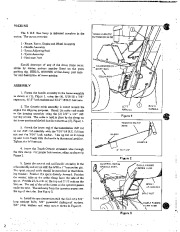
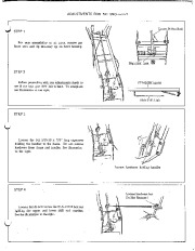
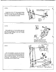
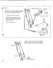
TOUCH-O-MATI C EXTENSION WI RE,i–+ J.– — ASSEMBLY 1. Fasten the handle assembly to the frame assembly as shown at (1), Figure 1, using the (4), 5/16-18 x 7/8 ” capscrews, 5/16 ” lock washers and 5/16 “-18 N.C. hex nuts. 2. The throttle cable assembly is coiled around the engine for shipping purposes. Uncoil the cable and attach to the housing assembly using the (2) 1/4 ” x 1/2 ” self· tapping screws. The cable is held in place by the clamp on the lower portion of the left handle as shown at (2), Figure 1. 3. Attach the lower end of the transmission shift rod to the shift rod assembly with the 7/16 “-14 N.C. full hex nut and the 7/16 ” lock washer. Line up rod so it moves up and down freely with the handle in the neutral position. Tighten the full hex nut. 4. Insert the Touch-O-Matic extension wire through the wire clamp. For proper belt tension, adjust as shown in Figure 2. 5. Insert the control rod and handle assembly in the tube assembly and secure with the 5/32 xI ” long cotter pin. The spout control cable should be assembled in the following manner: Position the spout directly forward. Position the control tube so the cable clamp faces the side of the spout. Provide 2 1/2 coils on the top and 2 1/2 coils on the bottom. The end of the cable closest to the operator passes under the tube. The end away from the operator passes over the top of the tube. See Figure 3. 6. Install the spout extension with the 5/16-18 x 3/4 ” long carriage bolts, 3/8 ” pyramidal shakeproof washers,. 3/8 ” plain washers and wing nuts as shown in Figure 3. CONTROL ROD & HANDLE ASSY. LEFT HANDLE RIGHT HANDLE Figure 1 TOUCH-O-MATI C WIRE HANDLE Figure 2 / CABLE PASSES OVER TUBE e ” r , ‘ Figure 3 2 · 161282 – FILM, SHIFT PATTERN 16124i.
Wikipedia’s page for Simplicity Outdoor
Publisher: www.simplicitymfg.com


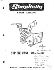 Simplicity 5 HP 551 219 463 2191 10805 10832 Snow Blower Parts Manual - Enlarge page 1 of 16
 2 of 16
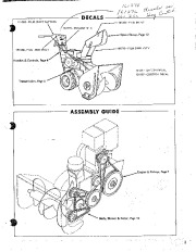 3 of 16
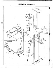 4 of 16
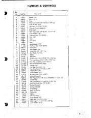 5 of 16
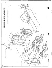 6 of 16
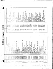 7 of 16
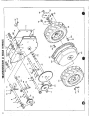 8 of 16
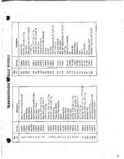 9 of 16
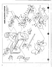 10 of 16
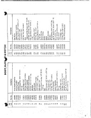 11 of 16
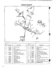 12 of 16
 13 of 16
 14 of 16
 15 of 16
 16 of 16