From inside (document excerpt):
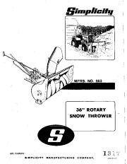
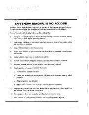
Simplicity 36 ” ROTARY SNOW THROWER SER. FORM·P49 SIMPLICITY MANUFACTURING COMPANY. lITHO IN U.S.A. SAFE SNOW REMOVAL IS NO ACCIDENT Improper use of snow removal equipment on the part of the operator can result in injury. To reduce this possibility. givecorilplete and undivided attention to the job at hand. Protect Yourself and OtnersBy Following These Safety Tips. 1. Disengage power and stop motor before cleaning discharge, removing obstacles, making adjustment, or when leaving operating position.
Snow Blower and Snow Thrower User Manual Free Download. Snow Removal Operator’s Manual. Free Manual Download PDF.
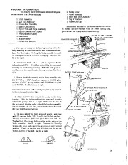
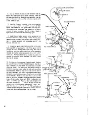
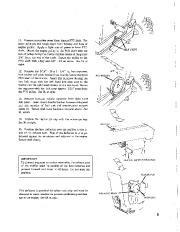
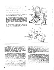
Never direct discharge at bystanders nor allow anyone in front of machine — debris may be hidden in the snow. Keep children and pets a safe distance away. Do not allow children to operate machine nor allow adults to operate it without proper instructions. Adjust height to clear gravel or crushed rock surface. Exercise caution to avoid slipping or falling, especially when operating in reverse: Know the controls and how to stop quickly — read the owner’s manual. Handle gasoline with care — it is highly flammable. a. b. Use approved gasoline container. Never add gasoline to a running motor — fill tank out of doors and wipe up spilled gasoline. Replace gasolinecapsecutely. Open doors if motor is run in garage — exhaust gases are dangerous. Disengage all clutches and shift into neutral before starting motor. Keep hands, feet and clothing away from power driven parts. 10. Use a grounded three wire extension cord for all plug-in electricllnits. 11. Keep machine in good operating condition and keep safety devices in place. PACKING INFORMATION The Rotary Snow Thrower is delivered complete in one carton. The Carton contains Hitch Assembly Lift Rod Assembly Clutch Rod Assembly Spout Control Rod Spout Tube and Rope Assembly Spout Control Rod Support Heat Deflector Clamp Skid Shoes Engine Pulley Clutch Rod Bracket Pulley Cover Spout Assembly Body and Rotor Assembly Bag of Hardware Winter Gas Cap’ Should any shortage of the above items occur, advise by stating packers number listed on green packing slip, part number and description of items missing. TOP OF BELT GUARD MUST HIT UNDERSIDE OF HOUSING. 1. For ease of access to the bearing housing rotate the body assembly so that front of the unit is flat on work SUfface. See Ill. at right. Block up the body assembly to avoid its moving or falling while it is in this upright position. See Ill. at the right. 2. Loosen the 5/16 – 18 x 1 – 1/2 ” 19. capscrew, 5/16 ” lockwasherand 5/16 – 18 full hex nut holding the belt guard assembly to the bearing housing. Slide the belt guard assembly out of the way along the bearing housing. See Ill. at right. 3. Secure the hitch assembly to the body assembly with (2) 3/8 “·24 x 1-1/2 ” long hex capscrews, (2) 3/8 plain washers, (2) 3/8 ” spring washers and 3/8·24 hex nut, full lock, 3/8 “-24. See illustration at right. It is necessary for the hitch assembly to pivot so be sure not to fasten the hardware too tight. 4. Place the “V ” belt around the pulley in the body housing. Slide the belt guard back to its normal position around the pulley. See Ill. at right. Make sure the top of the belt guard hits the under side of the housing assembly. See Ill. at right. At this time, secure the hardware loosened for Step 2 of these instructions. 5. On each side of the body assembly attach a skid shoe with (2) carriage bolts, 3/8 – 16 x 3/41g. (2) plain washers, 3/8, (2) lockwashers, 3/8 ” and (2) full hex nut, 3/8. 16. The heads of the carriage bolts must be on the inside of the body assembly. See Ill. at right. Remove the blocking holding the rotor body assembly and return it to its normal position. Check to see that the skid shoes are flat on the bottom surface of the skid. See Ill. at right. RIGHT WRONG 3 6. Line up the clip on the spout of the rotor body as· _ __ sembly with the notch on the spout assembly. With the clip and notch lined up. place the spout assembly over the spout of the rotor body assembly and rotate slightly right or left. See Ill. at right. 7. Assemble the spout extension to the spout assembly using two each of 5/16 ” – 18 x 3/4 “, carriage bolt, 3/8 ” special hex lockwasher, 3/8 “plain washer and wing nuts. The points of the special hex jock washer are to face in towards the spout extension.
Wikipedia’s page for Simplicity Outdoor
Publisher: www.simplicitymfg.com


 Simplicity 563 36-Inch Rotary Snow Blower Owners Manual - 1 of 12
 Simplicity 563 36-Inch Rotary Snow Blower Owners Manual - 2 of 12
 Simplicity 563 36-Inch Rotary Snow Blower Owners Manual - 3 of 12
 Simplicity 563 36-Inch Rotary Snow Blower Owners Manual - 4 of 12
 Simplicity 563 36-Inch Rotary Snow Blower Owners Manual - 5 of 12
 Simplicity 563 36-Inch Rotary Snow Blower Owners Manual - 6 of 12
 Simplicity 563 36-Inch Rotary Snow Blower Owners Manual - 7 of 12
 Simplicity 563 36-Inch Rotary Snow Blower Owners Manual - 8 of 12
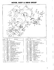 Simplicity 563 36-Inch Rotary Snow Blower Owners Manual - 9 of 12
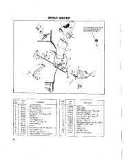 Simplicity 563 36-Inch Rotary Snow Blower Owners Manual - 10 of 12