From inside (document excerpt):
·Simplicity 42 ” ROTARY SNOW THROWER SER. FORM-P52 12145171910 lIT.HO IN U.s.A. SIMPLICITY MANUFACTURING COMPANY. INC· holding the rotor body ,assembly and return it to iis.nor; “a!·. .position.
Snow Blower and Snow Thrower User Manual Free Download. Snow Removal Operator’s Manual. Free Manual Download PDF.
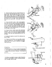
Check to iee tliat ‘ Ie’ skid shoes’ ar ‘flat ‘on at fight ‘. ‘ , RIGHT WRONG, 3 .’ .A 6. Line up the clip on the spout of the rotor body assembly with the notch on the spout assembly. With the clip and notch lined up, place the spout assembly over the spout of the rotor body assembly and rotate slightly right or left. See Ill. at right. 7. Assemble the spout extension to the spout assembly using two each of 5/16 ” – 18 x 3/4 ” carriage bolt, 3/8 ” special hex lockwasher, 3/8 ” plain washer and wing nuts. The points of the special hex lock washer are to face in towards the spout extension. See Ill. at right. Apply a light coat of oil to the neck of the discharge spout. 8. Install the rod guide support to the top hole of the bracket of the rotor body assembly. Fasten the rod guide support on the outside of this bracket using one each 3/8 ” 16 x 1 – 1/4 hex capscrew, 3/8 ” lockwasher and 3/8 ” – 16 hex nut. See Ill. at left. 9. Attach the spout control tube assembly to the rotor body assembly by pushing the rod of the spout control through the nylon bearing of the rotor body. For ease of installation, push the spout control rod as far as possible through the bearing before securing it with a 1/8 ” x 3/4 ” cotter pin. Now pull back on the control rod until it is possible to insert and secure the other 1/8 ” x 3/4 ” cotter pin. See Ill. at right. 10. Position the discharge spout directly forward. Position the control tube so the cable clamp is facing out. See Ill. at right. Provide 2-1/2 coils below the clamp and 2-1/2 coils above the clamp. The end of the cable above the clamp (closest to operator) passes under the tube and around the spout assembly. Place the loop of the cable over the stud of the spout assembly. The end of the cable below the clamp (closest to rotor body) passes over the tube and around the spout assembly. Place the loop end of the cable over the stud on the spout assembly and secure with a cup washer (edge of slip washer faces out), 5/16 – lockwasher and 5/16 – 18 full hex nut. Place the liner and rod guide over the spout control rod. Secure the rod guide to the outside of the rod guide support with a 5/16 ” – 18 x 1- 1/4 ” long hex capscrew and a 5/16 ” – 18 full hex lock nut. Tighten securely enough to permit spout control rod to he turned with slight pressure applied. See Ill. at right. ” _wL, I PECIAL H,EX LOCKWASHER 3/ LAIN WASHER ROTOR BODY ASSEMBLY 0 o (} ROD 41u ” GUIDEJ :IN:E R ; ;:: J’ ) CUP /1 /1/ …
Wikipedia’s page for Simplicity Outdoor
Publisher: www.simplicitymfg.com


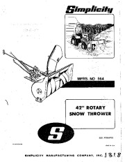 Simplicity 564 Snow Blower Owners Manual - 1 of 12
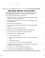 Simplicity 564 Snow Blower Owners Manual - 2 of 12
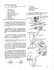 Simplicity 564 Snow Blower Owners Manual - 3 of 12
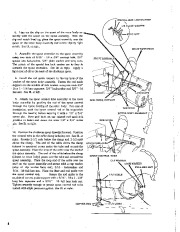 Simplicity 564 Snow Blower Owners Manual - 4 of 12
 Simplicity 564 Snow Blower Owners Manual - 5 of 12
 Simplicity 564 Snow Blower Owners Manual - 6 of 12
 Simplicity 564 Snow Blower Owners Manual - 7 of 12
 Simplicity 564 Snow Blower Owners Manual - 8 of 12
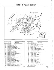 Simplicity 564 Snow Blower Owners Manual - 9 of 12
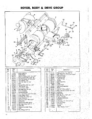 Simplicity 564 Snow Blower Owners Manual - 10 of 12