From inside (document excerpt):
Parts Manual Large Frame Walk-Behind Snowthrowers 9.5HP Snowthrowers Mfg. No. Description 1694589 1694597 9560E, 9.5HP Snowthrower 9560M, 9.5HP Snowthrower (CE) 10HP Snowthrowers Mfg. No. Description 1694590 1694598 1060E, 10HP Snowthrower 1060M, 10HP Snowthrower (CE) 11HP Snowthrowers Mfg. No. Description 1694591 1694599 1170E, 11HP Snowthrower 1170M, 11HP Snowthrower (CE) 12HP Snowthrowers Mfg. No. Description 1694592 1694600 1280E, 12HP Snowthrower 1280M, 12HP Snowthrower (CE) 13HP Snowthrowers Mfg.
Snow Blower and Snow Thrower User Manual Free Download. Snow Removal Operator’s Manual. Free Manual Download PDF.
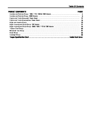
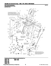
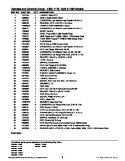
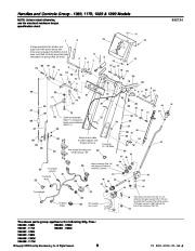
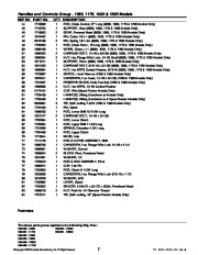
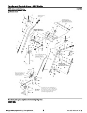
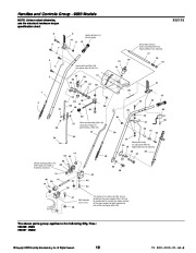
No. Description 1694593 1694601 1390E, 13HP Snowthrower 1390M, 13HP Snowthrower (CE) Part No.: 1731160 Rev. 11/2005 TP 400-4155-01-LW-S Table Of Contents PRODUCT COMPONENTS PAGES 4 8 12 16 20 22 26 30 34 36 38 Handles and Controls Group – 1060, 1170, 1280 & 1390 Models Handles and Controls Group – 9560 Models . Engine and Frame Group with Power Boost . Engine and Frame Group without Power Boost Auger and Impeller Group Auger Housing and Chute Group – 38 ” Models . Auger Housing and Chute Group – 9560, 1060, 1170 & 1280 Models . Traction Drive Group Wheels & Tires Group Decal Group . Headlight Group . Torque Specification Chart . Inside Back Cover Handles and Controls Group – 1060, 1170, 1280 & 1390 Models NOTE: Unless noted otherwise, use the standard hardware torque specification chart. 11 1 Linkage adjustment for traction and auger drive with power boost: with drive levers engaged, the bottom end of lower rods (Ref. 40 & 66) should be flush with bottom of springs (Ref. 39 & 68). 986724 Shift rod assembly (Ref. 71) must pivot freely on pivot blocks (Ref. 21). 27 34 35 36 37 32 67 66 65 59 64 65 Mount clutch cable to cable support, see Engine & Frame. See Auger Housing and Chute Group – 38 ” 34 44 Torque to 19 – 29 ft-lbs. 84 47 48 40 43 46 56 63 To engine ground Mount bushings (Ref. 78) with flange on inside of brackets, 3 places. 46 61 62 To engine plug 43 45 52 53 83 51 58 48 43 50 49 To headlight 57 59 To spout motor 54 Slot towards rear of unit. The holes in the frame for Ref. 51 are slotted so the gear support (Ref. 45) can be positioned to ensure the inside surface of the gear support is tight against the hub of the front gear (Ref. 50). 60 55 The above parts group applies to the following Mfg. Nos.: 1694590 – 1060E 1694591 – 1170E 1694592 – 1280E 1694593 – 1390E 1694598 – 1060M 1694599 – 1170M 1694600 – 1280M 1694601 – 1390M 2005 Simplicity Manufacturing, Inc. 4 TP 400-4155-01-LW-S Handles and Controls Group – 1060, 1170, 1280 & 1390 Models REF NO PART NO. 1 2 3 4 5 6 7 8 9 9 10 11 12 13 14 15 16 17 18 19 20 21 22 23 24 25 26 27 28 29 30 31 32 33 34 35 36 37 38 39 40 41 42 43 1727128 1668608 1928732 1668185 1725205A 1960471 1705899 1726422 1726317 1723965 1667800C 1724489 1925592 1930641 1935450 1933689 1678579 1705898 1701342 1960686 1726672C 1723935A 1718791 1677453 1727127 1725702 1664022 2834683 1933896 1678392 1726728 1960589 7075909 1726727A 1930591 1668121 2828704 2108775 1916621 1707452 1668526 1960093 1714084 1667588 QTY. DESCRIPTION
Wikipedia’s page for Simplicity Outdoor
Publisher: www.simplicitymfg.com


 Simplicity 9560 1060 1170 1280 1390 E M Snow Blower Parts Owners Manual - Enlarge page 1 of 42
 2 of 42
 3 of 42
 4 of 42
 5 of 42
 6 of 42
 7 of 42
 8 of 42
 9 of 42
 10 of 42
 11 of 42
 12 of 42
 13 of 42
 14 of 42
 15 of 42
 16 of 42
 17 of 42
 18 of 42
 19 of 42
 20 of 42
 21 of 42
 22 of 42
 23 of 42
 24 of 42
 25 of 42
 26 of 42
 27 of 42
 28 of 42
 29 of 42
 30 of 42
 31 of 42
 32 of 42
 33 of 42
 34 of 42
 35 of 42
 36 of 42
 37 of 42
 38 of 42
 39 of 42
 40 of 42
 41 of 42
 42 of 42