From inside (document excerpt):
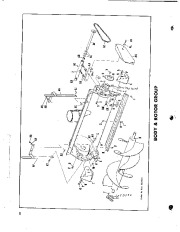
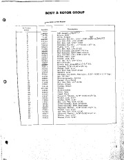
36 ” Rotary Snow Thrower ARTICLE 41:990187 SIMPLICITY MANUFACTURING COMPANY / PORT WASHINGTON, WIS. snow plow is shipped from the factory in 3 rtons. The largest carton contains the rotor hous::19, skid shoes, drift cutters, spout, “V ” belt for spout and the hot air deflector for the engine. The smaller carton contains the idler lever assembly, “V ” belt, pulley, woodruff key, 3 washers for the rotor drive shaft, push bar assembly, hardware for attaching the push bar to the snow plow, and the support bracket for the spout adjusting rod.
Snow Blower and Snow Thrower User Manual Free Download. Snow Removal Operator’s Manual. Free Manual Download PDF.
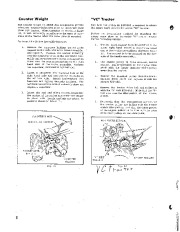
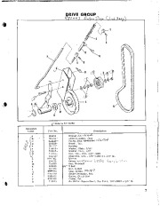
The third carton contains the spout adjusting rod, and the clutch rod. To assemble the snow plow, procede in the following sequence: 1. Assemble the push bar to the rear of the rotor ” “e Assembly 3. Assemble the drift cutters in place on each side of the rotor housing as shown in figure 3. housing, using 2 hex capscrews. The long capscrew (7/16 “-14 NC x 4 1/2 ” 19. ) and the spacer are used in the rear hole of the push bar as shown in figure 1. The other capscrew ( 1/2 “-13 NC x 23/4 ” 19. ) is used in the front hole of the push bar. Fasten the capscrews in place with lockwashers and hex nuts. Fig. 3 4. Apply a coating of light oil to the neck of the discharge spout mounting colar and install the spout in place on the rotor housing as shown in figure 4. The application of oil is necessary to prevent rust and to allow the spout to rotate freely. Clamp “V ” belt around the spout as shown in figure 4, and loop the belt around the adjusting pulley. To adjust tension of the “V ” belt, turn the hex nut at point “A ” in Figure 4. Avoid excessive tension. Spout Extension Rotor Housing Fig. 1 2. Assemble tire skid shoes to each side of the rotor housing as shown in figure 2. .Glamp–. VBelt Ad’u,ting Pivot Lever pu ( li Fig. 2 Fig. 4 5. Assemble the idler lever assembly and pulle. to the rotor drive shaft in the following manner: Three washers are shipped loose in the smaller carton; one washer has a larger hole or bore than the others. Assemble the washer (with the larger hole) to the rotor drive shaft. Slide the hub of the idler lever assembly over the rotor drive shaft. Note: The reinforcing bar welded to the hub and the idler lever is to face away from the pulley end of the rotor drive shaft. Assemble the two washers with the smaller hole to the end of the rotor drive shaft and place the woodruffkeyin its keyway on the shaft. Mount the pulley with the hub facing the idler lever assembly and secure in place with the’set screw. See figure 5. 2. Fasten the rod guide support to the right hand side of the tractor as shown in figure 7. Insert the adjusting rod into the rod guide and check to be sure that the rod guide does not bind or pinch as the spout adjusting handle must rotate freely. / ADJUSTING ROD Fig. 7 3. Assemble ROTOR DRIVE SHAFT ASSY. Fig. 5 the lower end of the adjusting handle to the fork assembly on the adjusting pulley. See figure 8. Installation For ease of attachment to the Model W tractor I follow the steps outlined below: 1. The snow plow push bar attaches to the front of the tractor frame as shown in figure 6. Loosen the 2 “T ” nuts on the push bar hitch and engage the front hitch rod securely into the front notch or groove on the lower front end of the tractor frame. Depress the tractor handles and the rear hitch rod will seat itself into the rear notch or groove on the tractor frame. When the hitch rods are well seated in the notches tighten the “T ” nuts securely. I Fig. 8 4. Place the “V ” belt in position on the engine drive shaft pulley and on the rotor drive shaft pulley. Note: “V ” belt runs under the idler pulley. See figure 9. Insert the offset end of the clutch rod into the hole on the idler lever and fasten in place with a hair pin cotter as shown in figure 9. I l Fig. 6 Fig. 9 4 , 5. Attach the upper end of the clutch rod to the clutch rod pivot lever located on the left side of the tractor transmission. See figure 10. The projecting pin on the rod socket assembly is to be inserted into the hole in the clutch rod pivot lever and held in place by a hair pin cotter. Adjus t the tension on the “V ” belt by loosening the set screw and sliding -collar “A ” in or out while the clutch lever is in disengaged position. Retighten the set screw and engage the clutch. Belt tension will be correct when approximately 1/4 ” clearance is. visible between collar “B ” and the end of the rod socket assembly when the clutch is engaged. Avoid excessive belt tension as it will only cause premature belt failure. Operation Operation of the rotor is controlled by the position of the clutch lever located on the left handle of the tractor. To operate the rotor, push the lever forward and up to the disengaged position and start the tractor engine. Be sure that the tractor transmission is in neutral position before starting the engine. Pull the clutch lever back and downward to the, engaged position and the rotor will operate as long as the tractor engine is running. Bear in mind that the rotor will be revolving as long as the clutch is engaged and the tractor engine is running. Exercise caution at all times, and attempt to remove ice or snow from the rotor housing ordischarge spout unless the clutch is disengaged and the tractor engine is stopped. The skid shoes on each side of the rotor housing are adjustable either up or down to suit the surface over which the plow is to be operated. For a smooth surface, loosen the nuts and set the shoes so that the lower edge of the rotor housing rides on the surface. For use over an uneven or rough surface, adjust the shoes for maximum lift. When using the plow, set the discharge spout so that the snow will be thrown with the wind and never into the wind. Throwing snow into the wind is apt to be a source of discomfort to the operator. To alter th direction of discharge, rotate the spout by means of the adjusting handle. The angle of discharge may be altered by loosening the wing nut on the discharge spout extension adjusting rod and moving the extension to the desired position. Retighten the nut. When operating the plow through excessively heavy drifts of snow, depress the tractor handles and raise the plow while taking the first pass through the drift. Then lower the plow and go through the drift again.
Wikipedia’s page for Simplicity Outdoor
Publisher: www.simplicitymfg.com


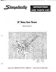 Simplicity 990187 36-Inch Snow Blower Owners Parts Manual - 1 of 12
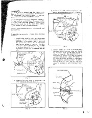 Simplicity 990187 36-Inch Snow Blower Owners Parts Manual - 2 of 12
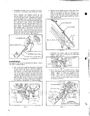 Simplicity 990187 36-Inch Snow Blower Owners Parts Manual - 3 of 12
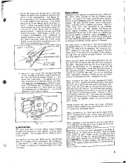 Simplicity 990187 36-Inch Snow Blower Owners Parts Manual - 4 of 12
 Simplicity 990187 36-Inch Snow Blower Owners Parts Manual - 5 of 12
 Simplicity 990187 36-Inch Snow Blower Owners Parts Manual - 6 of 12
 Simplicity 990187 36-Inch Snow Blower Owners Parts Manual - 7 of 12
 Simplicity 990187 36-Inch Snow Blower Owners Parts Manual - 8 of 12
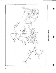 Simplicity 990187 36-Inch Snow Blower Owners Parts Manual - 9 of 12
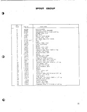 Simplicity 990187 36-Inch Snow Blower Owners Parts Manual - 10 of 12