From inside (document excerpt):
Form No. 102489 Operating Instructions for: 014-00071B 014-00072B 016-00029 016-00030 1819 1820 61146 61147 ADCE-61146 D-01001AA D-01002AA Mobile Floor Crane Max. Capacity 014-00071B 016-00029 1819, 61146 ADCE-61146 D-01001AA 2,200 lbs. 1,650 lbs. 014-00072B 016-00030 1820, 61147 D-01002AA Heavy Duty Boom retracted Boom extended 4,400 lbs. 3,300 lbs. Safety Precautions CAUTION: To help prevent personal injury and/or equipment damage, Read and carefully follow the safety precautions and operating instructions for this floor crane and the pump and ram used with this floor crane.
Power Tool User Manual Free Download. HAVC Operator’s Manual. Auto AC Lift Power Free Instruction Manual Download PDF.
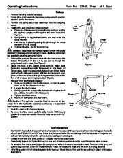
Most problems with new equipment are caused by incorrect operation or assembly. Wear eye protection that meets the requirements of ANSI Z87.1 and OSHA. Do not raise the boom with the legs in the upright position; the legs must be pinned through the cross member. The maximum relief valve pressure setting of any power source used with this floor crane must not exceed 8,800 PSI. Never attempt to lift a load heavier than the rated capacity of the crane boom, because overloaded equipment can fail. Stay out from underneath a load being lifted or suspended. To prevent tipping: do not lift or move a load that has a center of gravity extending beyond the legs or wheels; do not move a loaded crane unless the load has been lowered as close to the floor as possible; use extreme caution when moving a loaded crane on an incline or around a corner, because the load can swing out beyond the wheels and cause the crane to tip over. Do not modify this floor crane. If a modification is needed, contact OTC Division Technical Services. The owner of the crane is responsible for ensuring that procedures are followed according to federal, state, and local safety regulations. Sheet No. 1 of 1 SPX Corporation Issue Date: Rev. B, 7-31-02 Operating Instructions Setup 1. Remove banding material and tape. 2. Locate pins, chain assembly, and small parts packed in a carton attached to the floor crane. 3. Remove the pump and hose assembly from the shipping carton. 4. Position the legs under the cross member: a. Grasp one of the legs, and remove the leg catch pin holding the leg in an upright position against the crane mast. See Figure 1. b. Slowly swing the leg back and down, and then under the cross member. c. Lock the leg in place by sliding the pin through the cross member and into the leg. d. Repeat Steps 4a – 4d for the other leg. Caution: Legs must be locked in place under the cross member; if the legs are not locked in place, the floor crane can tip, possibly causing personal injury. 5. Arrange the pump on the crane mast with the hose end on the bottom. Thread four 1/4 dia. x 1 ” lg. cap screws through the pump base into the mast. See Figure 2. 6. Attach the hose to the bottom of the cylinder. Note: Seal hydraulic connections with Bakerseal or one layer of Teflon tape. Apply the tape carefully to prevent it from being pinched by the fitting and broken off inside the pipe end. Loose pieces of tape could travel through the system and obstruct the flow of oil or cause jamming of precision-fit parts.


 SPX OTC 072B 016 00029 016 00030 1819 1820 61146 61147 ADCE 61146 D 01001AA D 01002AA Mobile Floor Crane Max Capacity 014 0007 Owners Manual - 1 of 2
 SPX OTC 072B 016 00029 016 00030 1819 1820 61146 61147 ADCE 61146 D 01001AA D 01002AA Mobile Floor Crane Max Capacity 014 0007 Owners Manual - 2 of 2