From inside (document excerpt):
3/4 ” Electric Sprinkler Valve with Anti-Siphon Backflow Preventer, Model No. 53285 Installation & Service Instructions Thank you for choosing the Toro 3/4 ” electric anti-siphon valve for your automatic sprinkler system. Your new valve has been specifically designed for ease of installation, adjustment and service. It can be operated automatically by any sprinkler control timer with 24 VAC output as well as manually at the valve.
Lawn Sprinkler User Manual Free Download. Irrigation Free Instruction Manual Download PDF.
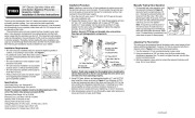
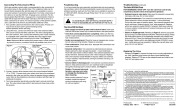
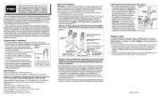
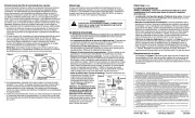
The anti-siphon valve not only controls the flow of water to your sprinklers, it also prevents contaminants from siphoning back into the fresh water supply after the sprinklers are shut off. This important safety feature, called an Atmospheric Vacuum Breaker (AVB), must be correctly installed to function properly. Therefore, before starting the valve installation, we urge you to read through these instructions and the Toro Automatic Sprinkler Planning and Installation Guide available from your retailer. Installation Procedure Note: Installing a manual shut-off valve between the water source and the sprinkler valves is recommended. This will enable the sprinkler system to be easily serviced and/or drained for winterization without interrupting the household water supply. 1. From the shut-off valve, route 1 ” IPS SCH 40 PVC pipe to the sprinkler valve installation site. 2. Prepare the threads of one 1 ” slip x 3/4 ” male thread adapter and one 3/4 ” slip x 3/4 ” male thread adapter with 2 wraps of PTFE tape. Install the 1 ” male adapter into the valve inlet and the 3/4 ” male adapter into the valve outlet. See Figure 2. Tighten the adapters securely. Do not over-tighten! Caution: Use only PTFE tape on threaded valve connections. Pipe dope will damage plastic components. Figure 2 Manually Testing Valve Operation 1. To manually test valve operation, turn Figure 3 the solenoid (indicated in Figure 3) slowly by hand counterclockwise 1/2 Increase turn. (Turning the solenoid further will Flow remove it from the valve.) The valve should open within 5 seconds. To close Solenoid Manual the valve, turn the solenoid clockwise Off until snug. Do not over-tighten! Manual On Note: It may take up to 60 seconds for AVB the valve to close. A small amount of Cap water may discharge from the AVB cap when the valve opens and closes. Refer to the “Troubleshooting ” procedures if the valve does not open or close properly. Decrease Flow Flow Control 1 ” Slip x 3/4 ” Male Thread Adapter To Additional Valves 3/4 ” Slip x 3/4 ” Male Thread Adapter 1 ” Schedule 40 PVC 3/4 ” Class 200 PVC 1 ” Slip x Slip x Slip Tee 3/4 ” Slip x Slip Elbow 3/4 ” Class 200 PVC To Sprinklers Flow Shut-Off Valve 1 ” SCH 40 PVC From Water Source Adjusting The Flow Control The valve is set for maximum flow at the factory and in most cases will not require additional adjustment. However, if a flow or pressure reduction is desired, refer to Figure 3 and use the following procedure. 1. Turn the solenoid 1/2 turn counterclockwise to open valve. 2. Using a screwdriver or 3/8 ” nut driver, turn the flow control slowly clockwise to decrease flow. To reset to a higher flow rate, turn the flow control counterclockwise. 3. With flow adjusted, close valve by turning the solenoid clockwise until snug. Do not over-tighten! Installation Requirements · The valve must be installed at least 6 ” above the highest sprinkler it controls, or according to local codes. See Figure 1


 Toro Owners Manual - 1 of 6
 Toro Owners Manual - 2 of 6
 Toro Owners Manual - 3 of 6
 Toro Owners Manual - 4 of 6
 Toro Owners Manual - 5 of 6
 Toro Owners Manual - 6 of 6