From inside (document excerpt):
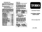
Starting System Test This is an excellent test to use when a “slow crank/no start ” problem is encountered. It will tell you if the problem is due to an electrical open, short or high resistance in the starter circuit. NOTE: The battery condition and the state of charge must be checked before testing the starter system. Tool(s) required: Digital Multimeter and Inductive Ammeter (AC/DC Current Transducer).
Lawn Mowing User Manual Free Download. Power Lawn Mower Free Instruction Manual Download PDF.
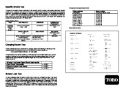
Test instructions: Properly connect the inductive Ammeter to the multimeter ( refer to the manufacturers instructions). Set multimeter on Volts scale. With the key off place the inductive ammeter around the main negative (-) battery cable and read the meter prior to activating the starter system. Adjust the meter to read zero ( if applicable). Crank the engine for at least 3 seconds and record the results. Battery Test Use a Digital multimeter to measure the voltage between the battery terminals. Set the multimeter to the DC volt setting. The battery should be at a temperature of 60° to 100° F (19° to 38° C). The ignition key should be off and all accessories turned off. Connect the positive (+) multimeter lead to the positive battery post and the negative (-) multimeter lead to the negative battery post. NOTE: this test provided a relative condition of the battery. Load testing of the battery will provide more accurate information. Typical Starter System Draw at 65°F (18°C) ° ° Groundsmaster 223-D Groundsmaster 224 Groundsmaster 325-D Groundsmaster 345 Groundsmaster 455-D Voltage Measured 12.6 V (or higher) 12.4 V 12.2 V 12.0V Battery Charge Fully charged (100%) 75% charged 50% charged 25% charged Commercial Products Greensmaster 3000 Reelmaster 223-D/5100-D Reelmaster 5300-D Reelmaster 335-D/3500-D Reelmaster 450-D/4500-D Workman 3200 Workman 3200-D Sand Pro 5000 Multi-Pro 1100 Hydroject 3000 215A 110A 210A 75A 230A 85A 215A 250A 230A 300A 90A 170A 125A 80A 110A Voltage Drop Testing This is a simple test that should be used to locate excess resistance in an electrical circuit. Tool required: Digital Multimeter DC volts setting. Test instructions: Connect the positive (+) test lead to the power (or most positive) side of the component, circuit or connection. Connect the negative (-) test lead to the ground (of least positive) side of the component, circuit of connection. Turn on the circuit to be tested and read the voltage. Remember – when performing voltage drop tests the circuit must be complete and activated to locate the resistance. ELECTRICAL SYSTEM POCKET GUIDE The Toro Company -1996 Voltage mums) Drop Specifications ( Maxi- High Amperage Circuits (>20A) 0.4 Volt feed side 0.4 Volt ground side Low Amperage Circuits …
Wikipedia’s page for Toro Company
Company Web Site: www.toro.com


 Toro Starting System Guide - 1 of 2
 Toro Starting System Guide - 2 of 2