From inside (document excerpt):
Installation Instructions Super 700 Series Sprinkler Introduction The versatile Super 700 Series Sprinkler is designed to meet a wide range of applications in both residential and commercial irrigation systems. For best results, read through the instruction manual completely first to familiarize yourself with the product specifications, recommended installation methods and adjustment procedures. Specifications Model S700 S700C S700S Inlet 3/4 ” FNPT 3/4 ” FNPT 3/4 ” FNPT Pop-Up Height (To Nozzle) 3-1/2 ” 3-1/8 ” 79.4 mm 79.4 mm Body Diameter 2-3/8 ” 2-3/8 ” 2-3/8 ” 1-3/4 ” 6.03 cm 6.03 cm 6.03 cm 4.45 cm Height (Overall)
Lawn Mowing User Manual Free Download. Power Lawn Mower Free Instruction Manual Download PDF.
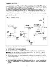
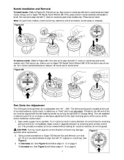
Installation Procedure The S700, S700C and S700 HP sprinklers are designed for installation in-ground, aligned perpendicular to the coverage area with the top of the cap level with compacted finish grade. When operated, the sprinkler riser will extend, positioning the rotating nozzle above the turf or ground cover. When turned off, the nozzle and riser will retract, by spring pressure, into the sprinkler body assembly. The S700S shrub sprinkler is designed for installation above ground on a riser, constructed from 3/4 ” (20mm) schedule 40 or 80 PVC or galvanized steel pipe, positioned perpendicular to the coverage area. Installation of a flexible connection between the sprinkler or shrub riser and the lateral line is recommended. Unlike a rigid connection, the flexible link enables easy, accurate positioning of the sprinkler and helps protect the PVC piping and fittings from breakage due to downward or lateral sprinkler movement. See Figure 1 for typical installation methods. Figure 1 – Installation Methods S700S S700 & S700C S700 HP 3/4 ” (20 mm) SCH 40 PVC, SCH 80 PVC OR GALVANIZED PIPE 3/4 ” THREADED COUPLING FUNNY PIPE 3/4 ” SxSxT TEE FUNNY PIPE FUNNY PIPE 3/4 ” SxSxT TEE 3/4 “MALE ELBOW (850-32) 3/4 ” SxSxT TEE 3/4 ” MALE ELBOW (850-32) 3/4 ” MALE ELBOW (850-32) Referring to Figure 1, install the sprinklers as follows: 1. Complete all pipe connections from lateral lines. 2. Thoroughly flush all dirt and debris from system. 3. Thread sprinkler onto 3/4 in. male NPT fitting and tighten by hand until snug do not overtighten. CAUTION: Use only TeflonTM tape on plastic threaded connections. Use of pipe dope or other pipe sealing compounds may damage plastic components. 4. Backfill soil around sprinkler or shrub riser. Thoroughly compact soil around components to maintain correct installation position. 5. If sprinkler nozzle is not installed, remove protective cover and install nozzle at this time. See “Nozzle Installation and Removal ” instructions on page 3. 6. Activate sprinklers and observe operation. If necessary, adjust part circle arc and/or spray radius as explained in following sections: “Part Circle Arc Adjustment ” (pages 3 – 5) , “Spray Radius Adjustment ” (page 6). 2 Nozzle Installation and Removal To install nozzle: (Refer to Figure 2A.) Pull lock pin up. Align arrow on nozzle top with slot in nozzle turret and insert nozzle. Using a coin or Super 700 Nozzle Tool & Wrench (89-1376), press and turn nozzle clockwise until seated in turret. Turn lock pin to align slot with “L ” (lock) on nozzle top (part circle models only).
Wikipedia’s page for Toro Company
Company Web Site: www.toro.com


 Toro Super 700 Installation Instructions - 1 of 10
 Toro Super 700 Installation Instructions - 2 of 10
 Toro Super 700 Installation Instructions - 3 of 10
 Toro Super 700 Installation Instructions - 4 of 10
 Toro Super 700 Installation Instructions - 5 of 10
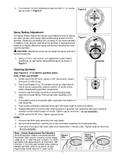 Toro Super 700 Installation Instructions - 6 of 10
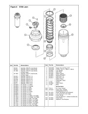 Toro Super 700 Installation Instructions - 7 of 10
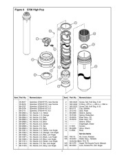 Toro Super 700 Installation Instructions - 8 of 10
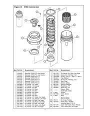 Toro Super 700 Installation Instructions - 9 of 10
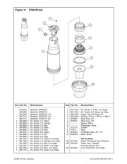 Toro Super 700 Installation Instructions - 10 of 10